I look over my order on the screen again. I'm ordering two copies of my board at about $70/board. I could have spent a few hours and built these boards for a few dollars in-house. But the vias would also have wires sticking through them, and there would be no solder mask.
I will have to wait two days for the fab house to make it, then another couple of days for shipping. Is this worth it? I look at my component list, which has grown to nearly eighty components. How will I put it all together?
I will have to wait two days for the fab house to make it, then another couple of days for shipping. Is this worth it? I look at my component list, which has grown to nearly eighty components. How will I put it all together?
There are many PCB fabrication services. AdaFruit has a list. Bob Alexander has a PCB cost calculator at PCBShopper.com - but it is missing a couple of suppliers, including Sunstone Circuits, where I finally got my boards.
I wanted a low quantity (2 boards for this run, with 5-10 for the next) fast turnaround (3-5 days) and a silkscreen because of the large number of components. Plugging these parameters rules out most of the batch and offshore producers, leaving a few choices:
I wanted a low quantity (2 boards for this run, with 5-10 for the next) fast turnaround (3-5 days) and a silkscreen because of the large number of components. Plugging these parameters rules out most of the batch and offshore producers, leaving a few choices:
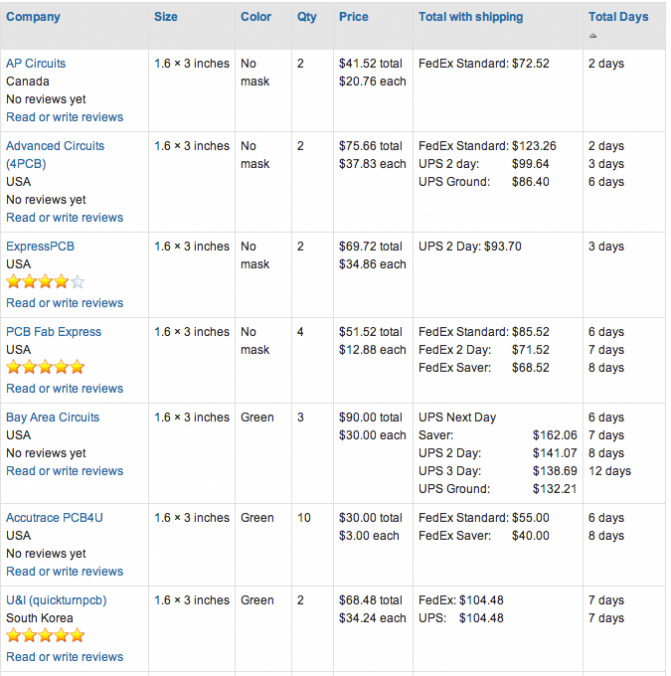
PCB cost calculator results - 1.6x3 inches, quantity 2, sorted by total days - there are 10 more, including OSHpark and Gold Phoenix, but all had longer lead times.
I ended up using Sunstone circuits for a couple of reasons.
- They provided a solder mask - unlike the cheapest producers.
- They were able to do a 4 day turn, using an expedite coupon and 2 day shipping ($32)
- The final total per board was ~$65 - competitive with the other services once their high shipping fees (which matter for such a small board order) were taken into account
- They had an up-to-date and streamlined web interface with an upfront price/time matrix, along with Eagle CAD specific instructions, design rules and Gerber export scripts. The last thing I wanted to do was pay for speed and have my design be held up, or worse, be done wrong. And I had never done a Gerber export before, so it helped to have some guidance.
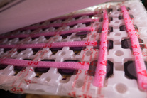
 The circuit board in the stencil jig
 For stencils I chose OSHStencils. The website reads my Eagle CAD files directly and previews the stencil. I paid $12 for a polyamide top stencil, $10 for a bottom stencil, $5 for a set of jigs, and $6 for USPS Priority Mail shipping - a total of ~$30 (including a discount) - in contrast to the $100+ that Sunstone offered. There are also ways to DIY the stencils (e.g. etch in aluminum sheeting from soda cans or similar) but for now a plastic stencil is fine, and my lead time is limited by the PCB anyways.
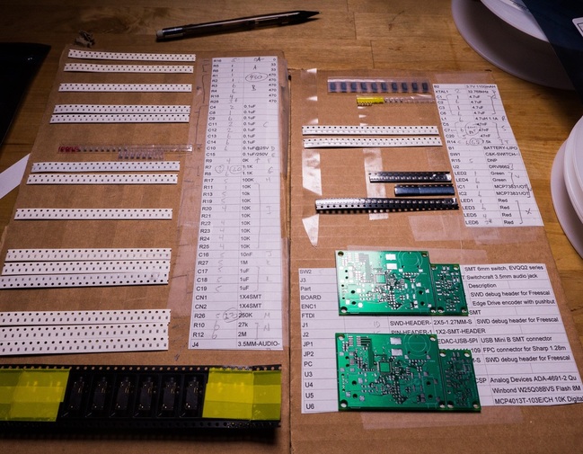
The picking board, with cut-tape parts, parts list and two copies of the PCB
Boards, stencils and components arrived within a couple of days.
First, I made up a picking board:
First, I made up a picking board:
- Export the bill of materials (BOM) from Eagle in CSV
- Import into a spreadsheet (e.g. Google Docs)
- Sort by part value (editing part values such as 0.1uF and 100nF to be the same)
- Tape the list to the board, and also put down double sided tape to hold the cut-tape parts
- For each set of parts, stick down the cut-tape holding the parts, find the region on the board (I split the board into 6 regions) that the part is in and annotate, and also annotate any part changes (e.g. substituting a 430 Ohm resistor for a 470 Ohm)
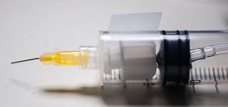 The syringe pick tool.
 I also realized that I couldn't use tweezers - it simply isn't possible to quickly pick up components from the tape. So I ran out to my local pet store and bought an aquarium pump ($10.00) and some tubing. I ended up having to modify the pump - drilling a hole into the pump chamber and mounting a tubing adapter using silicone glue.
For the picker, I modified a 10mL syringe I had on hand for another project. I drilled a hole in the plunger, stuck in the adapter, and drilled a small finger-hole to control the vacuum. I bent a small flat-ended needle, just the right size for 0603.
It took a little practice to get the fine motor control right (it's not totally natural to release by pulling your finger off of the hole - which itself generates a small vacuum that causes your fingertip to stick - hence the piece of Scotch tape) but it's easy enough.
To apply solder paste to the board, I taped the stencil down to the jig using some Scotch tape, put down a dollop of solder paste, and spread using the credit-card like spreader they supplied. Even though my spreading wasn't perfect (some paste got onto the solder-mask) it turned out not to matter too much.
It took about 30 mins to pick-and-place most of the components - and most of this time was in looking up where components were on the board. For later boards I may have to find a way that the component numbers are ordered on the board (right now they are ordered on the schematic from top-left to bottom right - but the board is scrambled compared to the schematic). And it would speed up a lot if I was doing a batch of boards.
Checking that all of the components were placed was easy - it was easy to spot solder-paste where a component was missing.
The board looked intact. But with a new PCB design there are always errors - it's more about catching the big ones before they cause damage. Here are the errors I found (so far)
- I ordered the wrong package for one of the analog op-amp chips I was using. It only affected the analog section, so I could still work with the board while waiting for the chip to arrive.
- When the on-off switch was turned to off, it was shorting the power to ground. Doh! Caught it before it blew up a battery. Lesson: don't use the common terminal for the positive rail! Temporary fix: desolder the switch, cut one of the terminals.
- The die-attach pad for the ICs were covered in soldermask - an oversight when I was laying out the package. It took me a couple of tries before I realized I had to press the chip down a little to set the pins, as it was floating above the soldermask - before that, the on-chip regulator would not start, a sign that something was wrong.
- I accidentally switched a power supply capacitor with a nearby resistor from the reset circuit. Surprisingly the circuit booted up, but it showed up as a flaky debugger connection. This probably took me six or seven hours to figure out - reworking various components, trying to track down the flakiness. Once I put the resistor and capacitor in place it worked perfectly.
- My circuit included a new element designed to pull a pin low to indicate that no headphone was plugged in. Unknownst to me, the pin I chose by default triggered a non-maskable interrupt, hanging the processor. After a lot of confusion (it worked while in the debugger mode, strangely enough) I sorted this out. Once I plugged a headphone into the jack (which de-asserts the pin) everything worked.
- I discovered, to my dismay, that I had ordered 50 of the wrong type of display - and at $12/each this was a $600 mistake! I hadn't checked the part number closely enough and only glanced through the datasheet. Not only was this display bigger and heavier, it was round (the 128x128 pixels were masked off) and required a +5V power supply. After some panic, I found the correct display in stock (but really expensive - nearly $18/display in small quantities), figured out how to RMA the incorrect displays, and put in a new order.
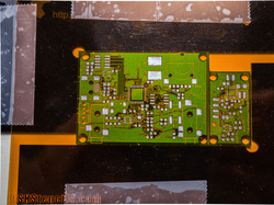
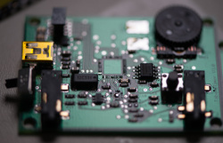 The board after reflow
 For my previous boards I used a hot-air rework station, but I wanted to try a different technique this time. SparkFun has a write-up of several techniques and seemed to like the electric skillet method the best. Not wanting to make room for a toaster oven in my apartment, I found inexpensive hotplate online.
The hotplate was almost too powerful. Even at a minimum setting, the surface quickly reached 250C and continued climbing. It was tricky to monitor since my IR heat gun gave different readings than a thermocouple, and the surface of the hotplate was much hotter than the top of the PCB where the joints were. Hooking up a temperature controller helped, but was finicky.
So I played it by ear - I flipped the switch, watched the temperature rise, and after about 30 seconds or a minute (e.g. when I saw it rapidly going through 120C), turned it off. I was nervous when the board started smoking and I began wondering what to do if it all caught on fire. I told myself it was just the flux in the solder paste. Eventually the solder melted, turning shiny and flowed into place.
 Wait - I wanted the square ones,
 not the round ones!
The board looked intact. But with a new PCB design there are always errors - it's more about catching the big ones before they cause damage. Here are the errors I found (so far):
- I ordered the wrong package for one of the analog op-amp chips I was using. It only affected the analog section, so I could still work with the board while waiting for the chip to arrive.
- When the on-off switch was turned to off, it was shorting the power to ground. Doh! Caught it before it blew up a battery. Lesson: don't use the common terminal for the positive rail! Temporary fix: desolder the switch, cut one of the terminals.
- The die-attach pad for the ICs were covered in soldermask - an oversight when I was laying out the package. It took me a couple of tries before I realized I had to press the chip down a little to set the pins, as it was floating above the soldermask - before that, the on-chip regulator would not start, a sign that something was wrong.
- I accidentally switched a power supply capacitor with a nearby resistor from the reset circuit. Surprisingly the circuit booted up, but it showed up as a flaky debugger connection. This probably took me six or seven hours to figure out - reworking various components, trying to track down the flakiness. Once I put the resistor and capacitor in place it worked perfectly.
- My circuit included a new element designed to pull a pin low to indicate that no headphone was plugged in. Unknownst to me, the pin I chose by default triggered a non-maskable interrupt, hanging the processor. After a lot of confusion (it worked while in the debugger mode, strangely enough) I sorted this out. Once I plugged a headphone into the jack (which de-asserts the pin) everything worked.
- I discovered, to my dismay, that I had ordered 50 of the wrong type of display - and at $12/each this was a $600 mistake! I hadn't checked the part number closely enough and only glanced through the datasheet. Not only was this display bigger and heavier, it was round (the 128x128 pixels were masked off) and required a +5V power supply. After some panic, I found the correct display in stock (but really expensive - nearly $18/display in small quantities), figured out how to RMA the incorrect displays, and put in a new order.
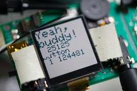 A working display. Yeah, buddy indeed!
 It took me about a day and a half to find the bugs. But once I found these, everything else worked just fine - the memory chip, the display, the processor.
I'm looking forward to the next steps - testing the encoder wheel and some of the analog electronics. However, I'm learning quickly. I've already decided in the next prototype to try replacing those components with the cheaply available MP3 decoder/amplifier chips available on market.
I hope this was helpful in illustrating the process of putting together a PCB. Happy PCBing!
 RSS Feed